|
What is a Variable Capacitor 75PF to 100PF?
|
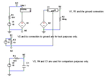
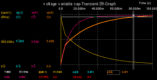
 A Variable Capacitor 75PF to 100PF is a capacitor whose capacitance may be intentionally and repeatedly changed mechanically or electronically. Variable capacitor 75 pf to 100 pf range are often used in cable tv descrambler circuits to set the resonance frequency, e.g. to tune a radio or cable tv box (therefore they are sometimes called tuning capacitors), or as a variable reactance, e.g. for impedance matching in video display, television and video game monitor projectors . A Variable Capacitor 75PF to 100PF is a capacitor whose capacitance may be intentionally and repeatedly changed mechanically or electronically. Variable capacitor 75 pf to 100 pf range are often used in cable tv descrambler circuits to set the resonance frequency, e.g. to tune a radio or cable tv box (therefore they are sometimes called tuning capacitors), or as a variable reactance, e.g. for impedance matching in video display, television and video game monitor projectors . In mechanically controlled 75 pf to 100 pf variable capacitors, the distance between the plates, or the amount of plate surface area which overlaps, can be changed. The most common form arranges a group of semicircular metal plates on a rotary axis (“rotor”) that are positioned in the gaps between a set of stationary plates (“stator”) so that the area of overlap can be changed by rotating the axis. Air or plastic foils can be used as dielectric material. By choosing the shape of the rotary plates, various functions of capacitance vs. angle can be created, e.g. to obtain a linear frequency scale. Various forms of reduction gear mechanisms are often used to achieve finer tuning control, i.e. to spread the variation of capacity over a larger angle, often several turns. A less common variant uses a set of concentric cylinders that can be shifted in or out of an opposing set of cylinders[1] using a screw. This form is preferred where the plates must be enclosed in a vacuum to allow for high voltages, since the movable part can be mounted on a flexible metal membrane that seals the vacuum chamber. Very cheap variable capacitors are constructed from layered aluminium and plastic foils that are variably pressed together using a screw. These so-called squeezers can’t provide a stable and reproducible capacitance, however. Small variable capacitors operated by screwdriver (for instance, to precisely set a resonant frequency at the factory and then never be adjusted again) are called trimmer capacitors. In addition to air and plastic, trimmers can also be made using a ceramic dielectric. The thickness of the depletion layer of a reverse-biased semiconductor diode varies with the DC voltage applied across the diode. Any diode exhibits this effect (including p/n junctions in transistors), but devices specifically sold as variable capacitance diodes (also called varactors 75pf, 100pf or varicaps) are designed with a large junction area and a doping profile specifically designed to maximize capacitance. Their use is limited to low signal amplitudes to avoid obvious distortions as the capacitance would be affected by the change of signal voltage, precluding their use in the input stages of high-quality RF communications receivers, where they would add unacceptable levels of intermodulation. At VHF/UHF frequencies, e.g. in FM Radio or TV tuners, dynamic range is limited by noise rather than large signal handling requirements, and varicaps are commonly used in the signal path. Variable capacitor 75pf to 100pf can also be used for frequency modulation of oscillators, and to make high-frequency voltage controlled oscillators (VCOs), the core component in phase-locked loop (PLL) frequency synthesizers that are ubiquitous in modern communications equipment. Voltage variable capacitor: It would seem trivial to create a voltage-variable capacitor. One could just pass parameter variables to a capacitor's capacitance. Simple …… or is it? If one does this, one creates a model that will exhibit steps in voltage across the capacitor if the capacitor value is changed. This is neither desired nor correct. This occurs due the model error, as a result of misusing/misapplying the fundamental capacitor equations. The defining equation for a capacitor is:
Clearly, the capacitance is a variable, a function of the controlling voltage. The other 'v' in dv/dt refers to the voltage applied to the capacitor. To keep them separate, we designate the controlling voltage as v2(t). Solving for dv/dt,
Integrating both sides results in:
Let the value of the capacitance C(v2(t)) be Co + v2(t)*Co, where Co is the value of the capacitor with va(t) = 0. It is convenient to nominally define the control voltage limits to between zero and one volts. This would however limit the capacitance variation to 2 * Co. One could allow va(t) to vary greater than 1 volt. We can get a little more flexibility by introducing another variable, k. The defining equation for C(v2(t)) becomes:
'k' could of course be fractional. Suppose the maximum v2(t) were 5V, however, if it were desired to make the maximum capacitance be perhaps 3.5 times the zero voltage value, k would be set to a value equal to 3.5/5 or 0.7.
|
|
other electronic intrests:

